Saturday, June 9, 2018

What's that noise?

I have received many enquiries bout the repetitive "grinding" noise one can here in the post;  Sunday, January 4, 2015.

Well, glad you ask, and now take a seat and get prepared to be bored to tears.......

The Hydropneumatic (no it's not air) suspension that Citroen developed in the 40's and that saw it's full deployment in all its glory in 1955 on the Citroen DS (like the one in this Blog), was a true marvel of engineering; that it also powered the brakes, power-steering (yes, in 1955)  and c-matic (manual-clutchless transmission) adds to its awe.

It is a constant flow system, that is, the pump is constantly turning, with oil flowing through the system and with a valve that opens at the required pressure to re-pressurise the accumulator; off-which the system relies to maintain pressurisation. This 7 piston pump is driven by the camshaft. So, in other words, the pump is constantly turning, most of the time under no pressure.


Being electric, we needed to save as much battery power as possible, so a constantly powered second motor (not the main propulsion motor), but a small high-torque unit, was not ideal. We re-engineered the system to include a high-pressure (around 1000psi) pressure-switch that at the right pressure, turned-off the electric motor and restarted it as the pressure fell to the lower-limit of pressure required.

So that "grinding" noise is a little, low-rev, high-torque motor that cuts-in at the right moment to repressurise the accumulator, maintaining the system at optimal pressure, under any condition. 

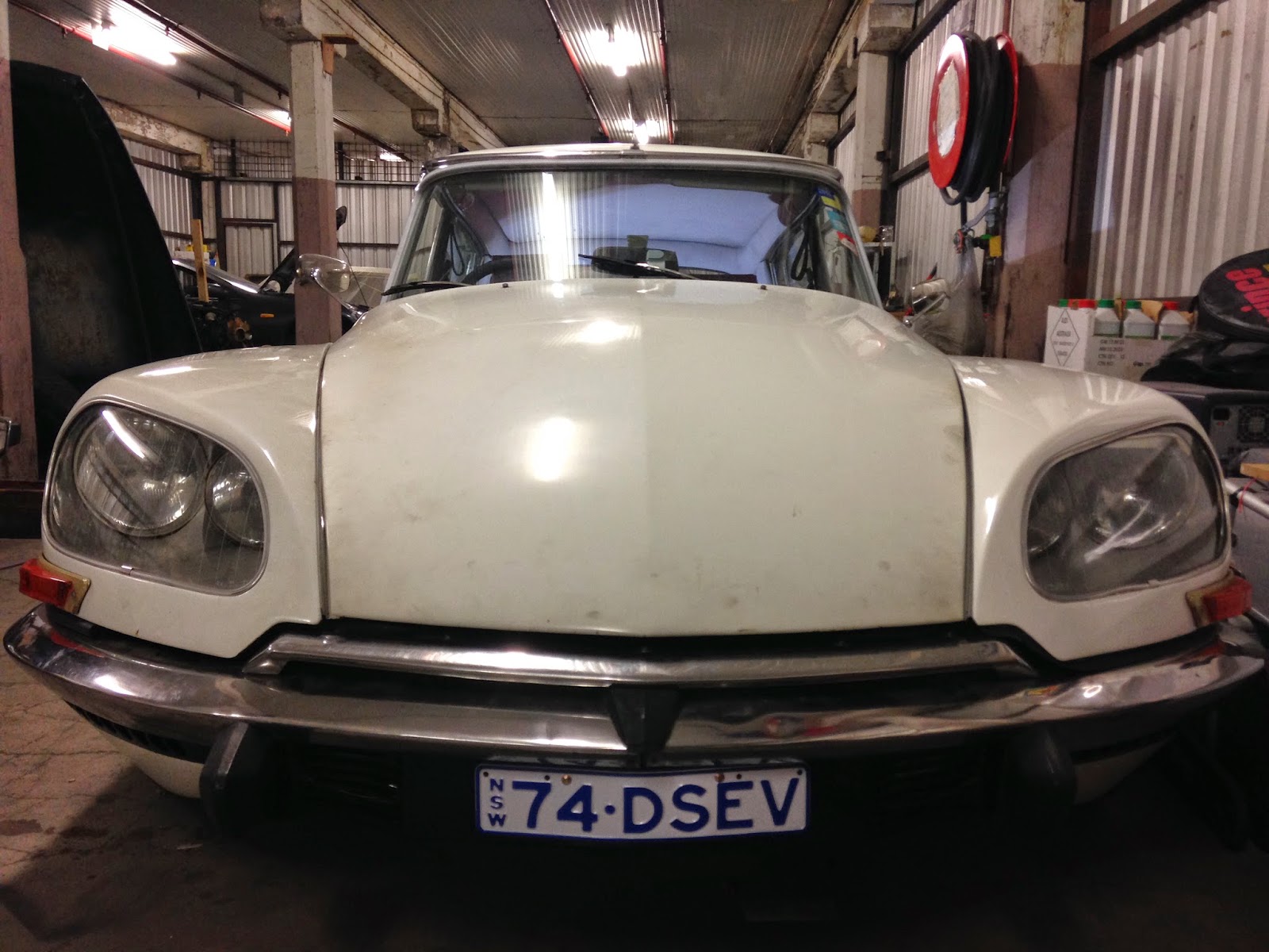
And yes, the magnificent 1974 Citroen DSev is still running great (not without ongoing enhancements) and is now being prepared to travel overseas for European touring.

Thursday, February 26, 2015

Sunday, January 4, 2015

2015 Update

So..... Happy new year to all!

What's been happening since our last 01/08/14 is the rhetorical question! Well, a lot of driving and a lot of tweaking..........


Overall, the Citroen DSev (74DSEV) has been working a charm. We have covered 480kms. It has consumed about $15 worth of fuel (electricity) and is eerily silent. "Today we did a range-anxiety" test and the BMS alarm came-on at 104kms.

So at 104kms, the BMS warned me to get to a charger. What a great effort without regen. My friends claim 20% improvement with regain, so my car has a range of around 120kms once I switch on regen. VERY HAPPY INDEED. 
But there is more, yes the BMS alarm came-on early as the pack voltage was still at around 87v. A long way from my theoretical 80% equivalent to 77v. 
So what went wrong? In fact it all worked a charm; everything worked as it should have. You will notice that indeed 2 cells (30 & 25) went below this theoretical value of 2.56v per cell and (one in particular got down to 2.41 by the time I covered 1 km to get home), so the alert was sounded. Had I exclusively relied on the controller software which indeed is great but gives the aggregate voltage value, I would have destroyed those 2 cells.
Now, all I have to do is test these 2 cells and maybe 15 and 20 as well and replace a couple of individual cells. Once sorted, the range should increase by a minimum of another 15kms. 
Before I do that, I shall charge and fully discharge the pack a few times to see whether this regulates those cells. Doubt it though. 
If indeed I have to replace these cells, I'll also replace the controller which I have been wanting to do. This will give me 30%+ increase in torque and I'll also create a bit more cooling for the motor which got up to 95c on a 30 degree day. 
The EVWest chill-plate and my 50c cut/in switch to circulate coolant kept the controller below 65c. Great outcome. 
I have an EV Grin spanning ear to ear!

Friday, August 1, 2014

Monday, May 12, 2014

A year ago tomorrow; the ICE engine came out!

As final builds go, this one is painstakingly slow!

All 96v cabling is done. Most of the BMS wiring is finished.

Above one can see the controller wired-in and having received the pin-outs for throttle and regen brake hall-effect pots, they are minutes away from being finished too :)

We still need to wire-up the charging circuit, although all the elements are now in place as you can see below.

Right at the front is the Elcon Charger, in front of a bank of cells in the green Joeys and behind that (in front of the rest of the green Joeys, are 2 x 12v batteries, flanked by 2 x 12v DCDC converters. Why 2 x 12v batteries. Well, the motor that now drives the hydraulic system in the DS EV is a 24v motor. It cuts in and out as required to top-up system. So, when the car is running as usual, the batteries are in parallel, providing the required 12v for the car electrics. However, when the pressure-switch cuts-in and gets the 24v motor going, solenoids (high-current relays), switch the batteries to in-series mode still allowing 12v to flow to the car electrics and 24v for the hydraulic compressor motor.Oh, the second DCDC converter is a backup and privides symmetry......

A "tray is being constructed that will protect the BMS's on top of the front cell range with a backing plate. This "tray" will be the space for a charging cable as well as other odds and ends.

The "tray" you see below is version 1 which has been scrapped while we produce a replacement. 


Under the bonnet is now covered with factory original padding (apart from the bit at the front which is usually uncovered:
Sorry.... Cannot seem to be able to rotate pic!
Oh, the 2 black strips above (on the bonnet ribs) are my new LED under-bonnet lights. And now for the icing on the cake, I am so happy with the result of the regen brake over the original Citroen DS "mushroom" brake. The theory is that standard braking will be taken-care of by the regen brake and in emergencies or immediate stop requirements, pushing the brake further, activates the very positive DS disk brakes.


Look Ma, clutch gone..... Yes, where the clutch pedal used to be, now is a space where one may comfortably rest the left foot. And for those of you with a keen eye, you may see that the clutch pedal is still in fact there, behind the carpet.


Oh! almost forgot……. One cannot forget the reverse switch. Here it is that red "safety" switch to the left of the steering wheel in the pic above.

And one last thing, the impact sensor, now mounted and ready for wiring, in the pic below.


Thursday, May 1, 2014

Final Build - more pics

Enjoy!
Notice Emergency Power Breaker, bottom-right

Another view

No, I do not like that colour either!


Good view of the Shunt and Contactor


Another View
My EV mates advising me and checking-on progress, over a pizza and watching Das Auto video.......
....Oh and getting their EVs charged-up :)


Tuesday, April 29, 2014

Final Build

Yes, plenty of progress since our last post. After a grueling Christmas/new year period constantly at it, we had to take a break from the project, recharge our energies (as-in human energies) before we could launch into the final build.

It was "fun" taking the Hydraulic Pump (that drives suspension, brakes and power steering in a Citroen DS) off the ICE and adapting it for an electric motor that now drives the Hydropneumatic system!


Well a bit of detail! We are utilising a 24v x 450w x 400 RPM bicycle motor to drive the pump (as kindly recommended by Henk the only other Citroen DS conversion I know off; in Holland). The previous motor I had acquired from China did not work as it was not geared; high-revving with no low-end torque. My friend Geoff machined pulleys for me an supplied a rubber toothed belt that now drives the pump off the motor.


Joey sample assembly

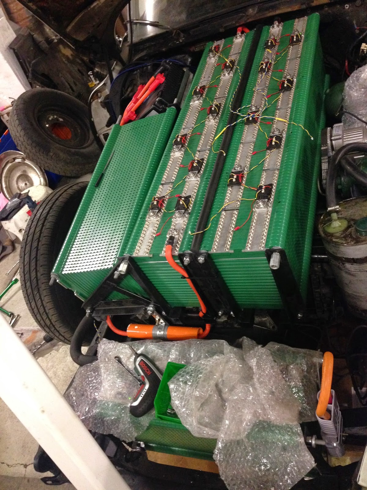
All 360 batteries that give us 240Ah @ 96v, are now assembled and mounted in the vehicle, mostly up-front on top of the motor and some in the place where the fuel tank used to reside. This gives optimal weight distribution and overall weight that matches that of the original vehicle. And what a sight it is.........
"Petrol Tank" Batteries
We have 5 x 240AH packs in the fuel tank, or 16v and 80v in the engine bay in the front. To a total of 96v @ 240AH.
First 2 sets of Batteries mounted
Yes, the air-horns are a standard issue with this vehicle. The Citroen DS was issued with a 2 stage horn system that still works well in our vehicle. When one pulls the horn lever, it sounds a normal horn. However, in case the "baguette camion" does not move out of the way "tout-de-suite", then pull the lever further and the air horns go for gold............
First 3 sets of Batteries mounted with Controller
No horrid steel battery boxes! The Green Joey kits seem to have worked a charm, with the self-mounting threaded rods that fasten the pack together while attaching it to the subframe we welded for it makes for relatively "easy" assembly ready to take cooling fans if required. We shall decide whether we need fans, after the first few trials.

Notice the redirected Gear Lever Mechanism, now underneath the Batteries
Being a reverse layout (gearbox in from of engine/electric motor), the gear lever linkage to the gearbox is via rod and cable. The rod selects the gears (5 speed plus reverse), while the cable shifts the "neutral" tunnel in between the various gears. The rod had to be redirected to move from over the ICE to under the batteries and you can just barely see it above; the crooked rod. Next, another set of batteries is mounted on top.

The (all so important) accumulator re-position from the old ICE
2 green spheres! For the non-Citroen initiated, that's the suspension....... The one at the bottom on the pic is the accumulator that maintains a standard pressure in the system and that is topped-up by the compressor as required. The other sphere is one of 4 that sit on each wheel and replace the traditional steel springs. They are half filled with Nitrogen (the springy part) and half with oil, interconnected to each other, the brakes and the steering to form the whole system. Not as complex as it sounds, but never the less, ingenious.

The Hall-Effect Throttle
In the 2 pictures above, but specifically in the one right above, one can see the hall-effect throttle that now replaces the fuel-injection system; still connected utilising the oriinal cable and accellerator pedal (keeping to the original wherever possible).

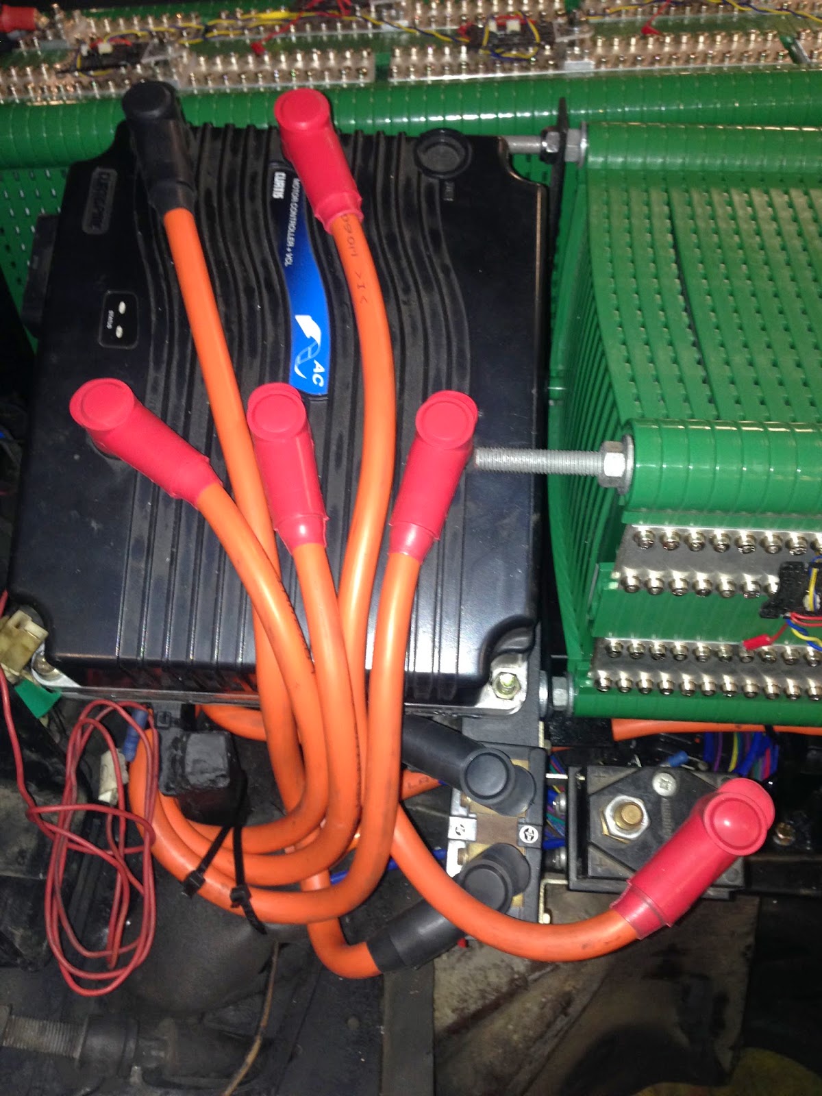
Wiring the Controller and Contactor
More views of the cabling including Controller (above and below) and the contactor above, right.
Curtis Controller

Another view of the Controller
That's right regen......... Well, yet to be seen what the best solution will be. So far, we are planning to have a regen/disks braking system.


Citroen does not use a traditional foot brake. Instead it utilises a "mushroom" similar to the old dimmer switches in old cars for those of us old enough to remember. In any case, it is a small mound on the floor that you merely squeeze millimetrically with your foot to generate amazing braking power. We have placed a hall-effect "throttle" pedal over the top of the "mushroom so that now the firs 75% of the travel is braking utilising regen to slow down the vehicle with the "mushroom" available just by moving the pedal further to activate the disk brakes for positive and aggressive braking requirements, hopefully only on rare occasions. All other times, braking is recharging the batteries.

This theory remains to be tested in practice. Now off to do some more cabling............... Stay tuned!