Tuesday, April 29, 2014

Final Build

Yes, plenty of progress since our last post. After a grueling Christmas/new year period constantly at it, we had to take a break from the project, recharge our energies (as-in human energies) before we could launch into the final build.

It was "fun" taking the Hydraulic Pump (that drives suspension, brakes and power steering in a Citroen DS) off the ICE and adapting it for an electric motor that now drives the Hydropneumatic system!


Well a bit of detail! We are utilising a 24v x 450w x 400 RPM bicycle motor to drive the pump (as kindly recommended by Henk the only other Citroen DS conversion I know off; in Holland). The previous motor I had acquired from China did not work as it was not geared; high-revving with no low-end torque. My friend Geoff machined pulleys for me an supplied a rubber toothed belt that now drives the pump off the motor.


Joey sample assembly

All 360 batteries that give us 240Ah @ 96v, are now assembled and mounted in the vehicle, mostly up-front on top of the motor and some in the place where the fuel tank used to reside. This gives optimal weight distribution and overall weight that matches that of the original vehicle. And what a sight it is.........
"Petrol Tank" Batteries
We have 5 x 240AH packs in the fuel tank, or 16v and 80v in the engine bay in the front. To a total of 96v @ 240AH.
First 2 sets of Batteries mounted
Yes, the air-horns are a standard issue with this vehicle. The Citroen DS was issued with a 2 stage horn system that still works well in our vehicle. When one pulls the horn lever, it sounds a normal horn. However, in case the "baguette camion" does not move out of the way "tout-de-suite", then pull the lever further and the air horns go for gold............
First 3 sets of Batteries mounted with Controller
No horrid steel battery boxes! The Green Joey kits seem to have worked a charm, with the self-mounting threaded rods that fasten the pack together while attaching it to the subframe we welded for it makes for relatively "easy" assembly ready to take cooling fans if required. We shall decide whether we need fans, after the first few trials.

Notice the redirected Gear Lever Mechanism, now underneath the Batteries
Being a reverse layout (gearbox in from of engine/electric motor), the gear lever linkage to the gearbox is via rod and cable. The rod selects the gears (5 speed plus reverse), while the cable shifts the "neutral" tunnel in between the various gears. The rod had to be redirected to move from over the ICE to under the batteries and you can just barely see it above; the crooked rod. Next, another set of batteries is mounted on top.

The (all so important) accumulator re-position from the old ICE
2 green spheres! For the non-Citroen initiated, that's the suspension....... The one at the bottom on the pic is the accumulator that maintains a standard pressure in the system and that is topped-up by the compressor as required. The other sphere is one of 4 that sit on each wheel and replace the traditional steel springs. They are half filled with Nitrogen (the springy part) and half with oil, interconnected to each other, the brakes and the steering to form the whole system. Not as complex as it sounds, but never the less, ingenious.

The Hall-Effect Throttle
In the 2 pictures above, but specifically in the one right above, one can see the hall-effect throttle that now replaces the fuel-injection system; still connected utilising the oriinal cable and accellerator pedal (keeping to the original wherever possible).

Wiring the Controller and Contactor
More views of the cabling including Controller (above and below) and the contactor above, right.
Curtis Controller

Another view of the Controller
That's right regen......... Well, yet to be seen what the best solution will be. So far, we are planning to have a regen/disks braking system.


Citroen does not use a traditional foot brake. Instead it utilises a "mushroom" similar to the old dimmer switches in old cars for those of us old enough to remember. In any case, it is a small mound on the floor that you merely squeeze millimetrically with your foot to generate amazing braking power. We have placed a hall-effect "throttle" pedal over the top of the "mushroom so that now the firs 75% of the travel is braking utilising regen to slow down the vehicle with the "mushroom" available just by moving the pedal further to activate the disk brakes for positive and aggressive braking requirements, hopefully only on rare occasions. All other times, braking is recharging the batteries.

This theory remains to be tested in practice. Now off to do some more cabling............... Stay tuned!

Friday, February 7, 2014

More Pictures - Charging Progress

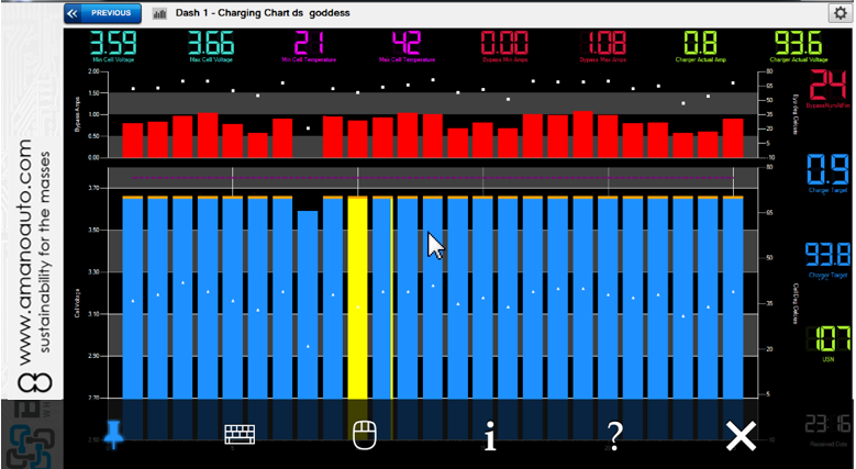
The BMS is on trickle charge, charging-up the batteries for the first time; doing it right ensuring that we get the maximum longevity from the batteries!

Day 1 after a few hours, 3 cells ready ........


Then about 4 hour stints for every pic below


Ready to go (all but one)! Yay.........

Wednesday, February 5, 2014

A Picture tells a Thousand Words

Well, a lot of progress. The devil is in the detail. All is now manufactured and what remains is the final rebuild, battery pre-charging and wiring.........

Less words and more pics to show progress.

The batteries in assembly:
Using the easy-to-build, green Joey A123 pouch holders and connectors.

Jaron and Mark installing the BMS:
Thank you guys.

The lights are flashing..... We have lift-off!
If you look closely you will see lights flashing in the first part of the video.

We've also received the regen brake pedal

It is no news to Citroen DS lovers that the DS does not have a brake pedal. Instead, it has a "mushroom" button, that DS owners know to thread on gently, as the movement required to go from no brakes to full lock-up is millimetric!

So we are introducing a brake pedal into our Electric DS. Why? Well, we have regen with our AC motor/controller combination. We shall utilise the pedal in the picture (originally manufactured as a throttle for EV deployment) to engage regen braking. The pedal will be setup so that when aggressive braking is required, the pedal pushes the "mushroom" as the pedal is pushed all the way.

This creates progressive braking that starts with, and mostly uses, regen and engages the powerful DS brakes if and when required. We believe that, with some level of precise setting, this will make for ideal braking with little usage of the disc brakes.

Friday, January 3, 2014

Preparing for the BIG unveiling........

And you, my BLOG reader get the first look-in!


New number plates ready.... yay!


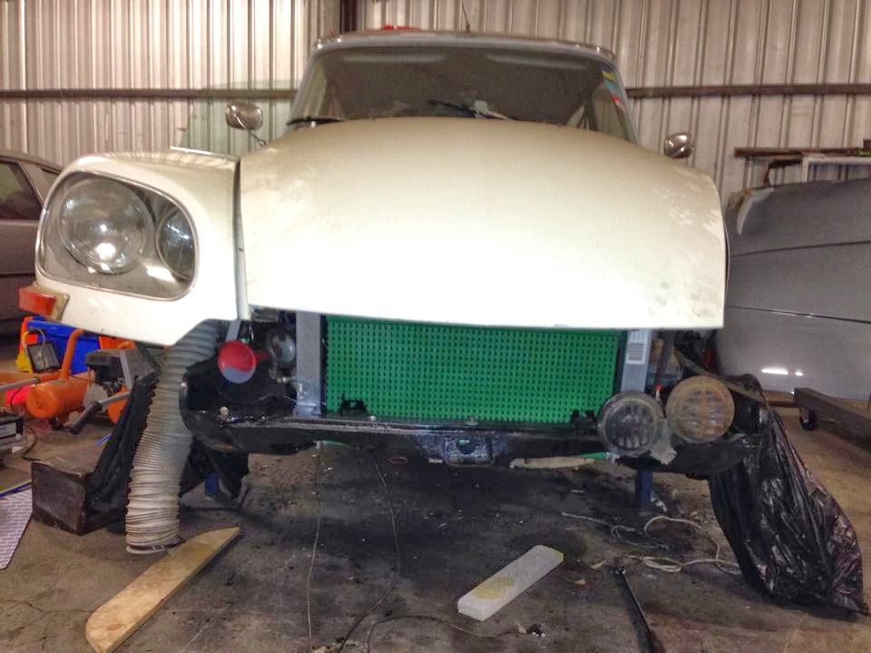
Many hours of work left. The vehicle is now fully-assembled as an EV (excluding wiring and BMS). However, this was done as an exercise of dimensioning (is there such a word?) everything. All the battery trays (Joey) are in (sans batteries) and all the various and many related components mounted in their right places. Here is the final mini project, Getting the hydraulic pump to work off an electric motor.


This is currently the Achilles Heel of the project for a number of reasons. Our motor is 12 volt 500w. Might be underpowered. Also, it is mounted laterally to the pump, driven by 2 belts. This might place too much lateral pressure on the bearing. We are going to test as is, as we wanted to utilise the original components (hydraulic pump). However, as my Citroen Expert Jason recommended, we might go to a CX pump which has a layout where I can connect the motor radially, easing pressure off the bearings.

Should all that fail, we shall resort to replacing the pump/motor assembly with a prepackaged electric pump as utilised in certain vehicles (we have already secured one). This would take a bit more engineering.

However, for now, as I said earlier, there remain MANY hours of work and we are truing to meet a January 31st deadline. What's there to do........?

Well, everything has to be disassembled. All the welded assemblies need to be finished-off, ground down and painted. The gearbox/motor assembly needs to be tightened and greased-up. Then the process of final assembly starts. All needs to go back in methodically, connecting the drive shafts, the hydraulics and wiring the whole vehicle (not a minor feat).

Oh, and we have to assemble and connect 360 batteries! Hours of brain-numbing work.

Once that's all done-up, and a few rust spots and scrapes cleaned-up, then the process of setting up the AC mpotor/controller and BMS starts. This "should" be quite straight-forward; but we have learnt that the devil is always in the detail.

Stay tuned....................

Saturday, December 28, 2013

Battery Trays are Here.... Yay!

To be exact, 1000 trays have arrived :) So..... I have a few spare ones!


As you would know from our earlier posts, we are using A123 pouches for this conversion. We thought long and hard about how to best mount 360 A123's! We decided, no welded boxes. Instead, we used these "Joey" trays for each battery. These trays lock-in together so you can have them in any configuration you like. 


So, we are assembling 30 (96v) packs of 12 cells (240ah). We shall be placing most under the bonnet (hood for you Americans) and some where the fuel tank (gasoline tank) used to reside. We should end-up at around the same weight as the original vehicle and similar weight distribution. Here is the look under the bonnet at this stage, The trays have no batteries in them. So they are light and as a result, easy to configure..........


Once I have the layouts worked-out and the mounting brackets manufactured, I shall then populate the trays with A123's. Very neat indeed.


  Oh, the challenges of having a Citroen DS Pallas as a donor vehicle are plentiful. You would remember that we are utilising the 5 speed gearbox with no clutch. This vehicle has "5 on the tree", better known as column shift. So, the linkage was right in the way of the battery location; so we had to remodel it. Here it is...


Ready for the battery trays to go-in as per above. I am smiling, this conversion is taking shape, and those trays (Joey) work a charm...........

Watch this space.

Wednesday, November 13, 2013

Coming together

This is the time where we are receiving all the various parts to assemble the final product and drive it! Seems like the most elusive target but is now getting closer.

The Citroen DS offers many challenges for EV conversion, but also provides a number of solutions. As an example, no need for vacuum pumps and other ancillaries to drive power brakes, etc....

The self-contained Hydropneumatic system does all the work related to suspension, power brakes, power steering and in some cases even gear changes! So all I need to do is to drive the Hydraulic pump that used to be driven by a pully off the ICE. I have 2 choices here, either find a self-contained pump/motor assembly and retrofit to the syste, or, as is my case, I am trialling a 12 volt 500w electric motor with a pully to the pump to see if I am able to draw enough power to drive the pump.


One might think that driving all the power requirements for suspension, brakes and steering off this motor (see pic) is a big ask, and this remains to be seen. However, once one understands how the Citroen system works, it becomes clear that maybe it is not such a big ask. Without going into too much detail, the pump is responsible to charge-up an accumulator up to and maintain it at 100psi. The accumulator is what is actually carrying the constant load; meaning that the motor will only be stressed as it tops-up which is surprisingly rather infrequent in a straight line as it is the steering that requires the most power.

My Citroen expert mate suggests I put in a second accumulator in the back to further diminish the load.

The batteries are on the way........................ 

We chose A123 20AH pouches as these seem to offer the best power-to-weight ratio. It is all about reducing weight when it comes to EVs. The lower the weight, combined with civilised driving and combined with regen, might produce the range we are after or better; 150kms.

We will be using 384 batteries to produce 240ah @ 96v. But how do we mount them. Well, this possibly was the most exciting part of the project. Decided to move-away from the standard "fit them in a box" approach, and instead build trays that like lego snap together and cradle the batteries in a protective if ventilated shell. The assembly will then be cooled down (as required utilising thermo-triggered fans) to ensure optimal operation.


This is unfortunately also another delay in proceedings. We are currently evaluating early samples so we may place final order. The design allows for these trays to snap together and for a long screw to hold batches together for final assembly. We believe this is a neat and logical solution for this challenge. More on this subject in the next episode.

Battery Management System


I have just ordered the various pieces that make-up the BMS system and, being in Australia, are only a hop, skip and a jump away. They will also kindly assist me with the configuration and installation. It would be remiss of me to not also mention and thank Jaron, who has been a constant source of great advice along the way.


The charger has also arrived and the DC to DC convertor is on the way.
I was recommended TC chargers. My mates have been using them successully.It arrived 2 weeks ago and is in the process of being mounted. Heat generation while charging is an issue. So it is important to find the right location where heat easily escapes. It will probably go under the front bonnet with an extractor fan.

The DC to DC convertor is also on the way. We wanted 600w which proved hard to get. So we are utilising 2 x 300w units instead.

Feels like we are on the final stretch...... Famous last words!

But from experience we are aware that the devil is in the detail and there will be many hurdles yet to face. We are cutting it too close to Christmas, which is a bummer as we wated to utilise the break to do most of the work.


Tuesday, October 8, 2013

The Fun Starts NOW!

OK, so templates, couplings, decisions and questionmarks!

We are now at the stage of mating the new AC31 EV Motor to the Gearbox Bell-Housing. This is probably the most technically accurate stage of the project. We need to mount the motor while ensuring that the coupling between the gearbox input splined shaft and the motor's "keyed" shaft is 100% accurate. Anything wrong here will result in broken shafts or bearings; not a desirable outcome.


We have made a template of the Flange that mounts the motor onto the gearbox. We are going the motor located by cutting a countersunk circle the diameter of the motor so it is always achieves positive alignment once the motor sinks into the circular cut.

And here's the finished product, motor and gearbox mated, ready to get mounted in the car.


Well, there was a hiccup. The mounting plate had to have its bottom third cut-off as it hit against the cross-member in the vehicle. Yet another wait however, all's well that ends well.

Unfortunately, this stage of getting from template to finished mounting plate and shaft connector, killed 4 months as we waited on 3rd parties to get the shaft connector machined.